5G networks rely on a variety of interfaces to ensure seamless communication between different network elements.
Each of these interfaces has a specific function that contributes to the overall functioning of a 5G network. Understanding these interfaces is crucial for getting the most out of a 5G network and unlocking its full potential.
In this article, we will explore the key 5G interfaces X2/Xn, S1/NG, F1, E1 and their functions, including N1, N2, N3 and N4 interfaces.

5G N1, N2, N3 and N4 Interfaces
The N1 interface is the interface for NAS signalling messages between the UE and the AMF. The N2 interface is the control plane interface between the 5G RAN and the 5GC.
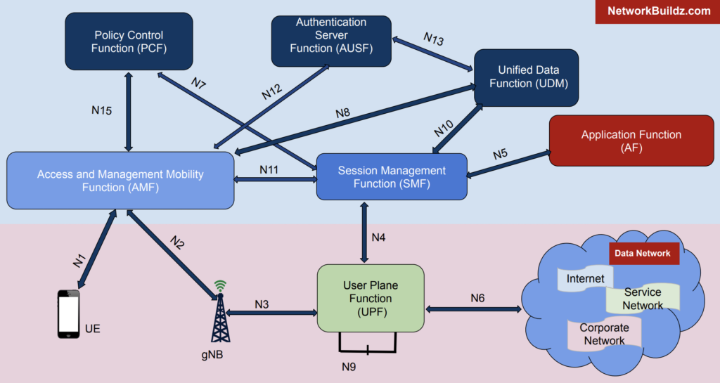
The N3 interface is the interface that supports user plane connectivity between the 5G RAN and the 5GC. The N4 interface is the interface between the SMF and the UPF.
5G N1 Interface
The N1 interface is responsible for the communication of NAS signalling messages between the user equipment (UE) and the access and mobility management function (AMF).
This interface also facilitates the transportation of NAS protocol messages to the UE in relation to network functions other than the AMF, such as session management NAS messages from the session management function (SMF).
The UE can connect to either a 5G or a non-3GPP access network through the N1 interface.
5G N1 Interface Functions are:
- Registration Management: managing the process of registering a UE to the network
- Connection Management: managing the connection between the UE and the network
- Session Management: handling UE messages and procedures related to session management, such as establishing and terminating sessions.
5G N2 Interface
The N2 interface is the interface that is used for communication between the 5G Radio Access Network (RAN) and the 5G Core Network (5GC).
Specifically, it is used for the control plane, which is responsible for setting up and managing connections between devices and the network.
The N2 interface carries NGAP (Next Generation Access Protocol) messages between the RAN and the AMF (Access and Mobility Management Function), which is one of the key components of the 5GC.
One important aspect of the N2 interface is that it has a unique termination point at the AMF for each individual user device (UE).
This allows for a separation of concerns between the AMF and other network functions that need to control RAN-supported services.
In other words, the AMF acts as a relay for session management information between the RAN and other network functions, such as the SMF (Session Management Function), without needing to be directly involved in the management of those sessions.
5G N2 Interface Functions are:
- Control plane interface between the 5G RAN and the 5GC
- Transport of NGAP (N2 Application Protocol) messages between RAN and AMF
- Unique termination point at AMF for each UE, regardless of number of PDU sessions
- Decoupling of AMF from other control plane network functions that need to control RAN-supported services
- Relaying of session management information between RAN and SMF by the AMF in a transparent manner.
5G N3 Interface
The N3 interface is responsible for providing user plane connectivity between the 5G RAN and the 5GC.
This interface is associated with each PDU session, and is used to transport user data between the RAN and the 5GC.
The N3 interface uses the GTP-U protocol, as specified in TS 29.281, to tunnel user data.
One of the key features of the N3 interface is the support for a new PDU session container, which is used for 5G user plane encapsulation.
Additionally, if the same PDU session is connected to multiple data networks, there will be a separate N3 instance for each connection.
5G N3 Interface Functions are:
- Provides user plane connectivity between the 5G RAN and the 5GC
- Associated with each PDU session
- Uses GTP-U protocol for tunneling user data
- Supports new PDU session container for 5G user plane encapsulation
- Separate N3 instance for each connection if the same PDU session is connected to multiple data networks.
5G N4 Interface
The N4 interface is the interface between the SMF and the UPF, SMF uses this interface to control the UPF and handle user plane packet forwarding, buffering, duplication, and dropping.
The SMF does this by creating, updating, and removing the N4 session context in the UPF and providing forwarding action rules with instructions to the UPF.
Additionally, the N4 interface also allows the SMF to:
- Control the activation, modification, and deactivation of QoS flows
- Monitor the status of the N4 session, including the status of the user plane and QoS flows
- Send and receive UP function related information, such as statistics and congestion status
- Handle security related issues and perform authentication and authorization for the UP function
- Provide the UPF with the necessary information for the UP function to perform the required actions for the user plane traffic, such as IP address allocation, and routing information.
Interface between RAN and Core Network (S1/NG)
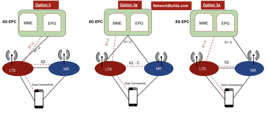
The S1 interface in LTE is reused in non-standalone operation between the eNB and the MME, while the NG interface is newly specified in standalone operation between the ng-eNB/gNB and the AMF.
The S1 interface supports functions such as bearer management, mobility management, and security. The NG interface, on the other hand, supports functions such as session management, mobility management, and security for standalone operation.
(X2/Xn) Interface: Between RAN Nodes
The X2 interface is used for communication between RAN nodes in non-standalone operation, such as between eNBs in LTE and between en-gNBs and eNBs in 5G.
The Xn interface is a new interface specified for communication between RAN nodes in standalone operation, such as between ng-eNBs and gNBs.
The extensions of X2 include functions for EN-DC (Evolved NodeB – Dual Connectivity) and flow control for split bearers in non-standalone operation.
The flow control function is used to split downlink data when using radio resources from multiple RAN nodes. In non-standalone operation, the information exchanged between RAN nodes is enhanced to optimize flow control.
The Xn interface, which is based on the X2 function, has enhanced UE context management for new QoS flow framework and network slice.
Additionally, the X2 interface and Xn interface also play a crucial role in facilitating the handover process between RAN nodes. This ensures that the connection is seamlessly maintained during the handover, and that there is minimal interruption to the user’s experience.
The X2 interface and Xn interface also support the exchange of measurements and measurement configuration between RAN nodes, which is necessary for radio resource management and interference management.
X2 and Xn Interface Functionalities:
- X2 interface is used between eNBs in LTE and between RAN nodes in non-standalone operation (between eNB and en‒gNB)
- Xn interface is newly specified between RAN nodes in standalone operation (between ng‒eNB and ng‒eNB/gNB and gNB/ng‒eNB and gNB)
- Extensions of X2 include functions adopting EN-DC and flow control for split bearers for non-standalone operation
- Flow control function, which was defined for LTE-DC split bearers in Release 12, is used to split downlink data when using radio resources of multiple RAN nodes
- Xn is based on the X2 function but with enhanced UE context management function for adopting new QoS flow framework and network slice.
RAN Nodes Interfaces: Functional Split and Open Interfaces (F1, E1)
The F1 interface is responsible for handling the user plane and control plane split between the gNB and the DU, while the E1 interface handles the control plane split between the DU and the CU.
The F1 interface is used for function split between the gNB and the DU in non-standalone operation, while the E1 interface is used for function split between the DU and the CU in standalone operation.
The functional split within a RAN node separates part of the functions in separate logical nodes, and open interfacing is used between these logical nodes.
The new functional split between Central Unit (gNB-CU) and Distributed Unit (gNB-DU) within gNB is defined to address the increased bandwidth required for transport between CU and DU.
The PDCP layer and above is located in the gNB-CU, and the RLC layer and below is located in the gNB-DU.
Additionally, there is a functional split of C-plane and U-plane in gNB-CU, which allows for placing C-plane function near gNB-DU and U-plane functions near Core Network or vice versa.
An open interface (E1) between the C-plane termination parts and U-plane termination parts of gNB-CU is specified to enable functional separation between different vendors.
The node that terminates the C-plane of gNB-CU is called gNB-CU-CP, and the node that terminates the U-plane of gNB-CU is called gNB-CU-UP.
5G eCPRI: Interface between PHY and Radio
The eCPRI interface is used to transport digital baseband samples between the PHY and the radio components in the RAN nodes. This interface is responsible for handling the transmission and reception of the radio signal.
The CPRI interface, originally developed for 4G, had vendor-specific implementations that caused issues for operators. eCPRI interfaces offer a more efficient solution as fewer interfaces are needed to test multiple 5G carriers.
eCPRI has been established as a standard interface for 5G O-RAN front-haul elements such as the DU.
Network disaggregation through functional split offers cost benefits, particularly with the implementation of new interfaces such as eCPRI.
Traditional RF interfaces are not cost-efficient when testing large numbers of 5G carriers, as RF costs increase rapidly.
5G Interfaces in Service-Based Representation
The network functions in the 5GC display their capabilities as services, which are provided to the consumer network functions through SBIs. Interactions between producer and consumer network functions follow two principal mechanisms:

- Request-Response: A network function consumer requests a service from a network function producer. This service can perform an action, provide information, or both. In the Request-Response mechanism, two network functions, consumer and producer, establish a communication channel and a one-time response is expected within a certain time frame.
- Subscribe-Notify: A network function producer displays a service to which one or more consumers are subscribed. The subscription request includes the notification endpoint of the consumer, and if there are periodic updates, the subscription request also includes the conditions that trigger the notification.

| 5G SBI Interfaces | Service Consumers |
| Namf | Peer AMF, SMF, SMSF, PCF, NEF, LMF, UDM, GMLC, CBCF, PWS-IWF |
| Nsmf | VSMF, HSMF, Peer AMF, AMF, NEF, PCF |
| Npcf | AMF, VPCF, AF, NEF, SMF, NEF, |
| Nnef | Application Function, SMF |
| Nnrf | AMF, SMF, UDM, AUSF, NEF, PCF, SMSF, NSSF, UPF, BSF, NRF |
| Nudm | AMF, SMF, SMSF, NEF, GMLC, AUSF |
| Nausf | AMF |
| Nnssf | AMF, NSSF in a different PLMN |
| Nsmsf | AMF |
| Nudr | UDM, PCF, NEF |
| N5g-eir | AMF |
| Nnwdaf | PCF, NSSF |
| Nlmf | AMF |
| Nbsf | PCF, NEF, Application Function |
| Nchf | SMF, PCF |

5GS and 4G EPC Interworking: N26 and S10 Interfaces
During 5GS and 4G EPC interworking, the N26 interface is used to exchange the UE context between an AMF in the 5GS and an MME in the EPS.
The S10 interface is used for UE context transfer between MMEs, interworking requires updates of the MME software.
The AMF and the MME select a combined PGW-C and SMF for all PDN connections that can move. As part of the interworking procedures, UEs support both EPS NAS and 5GS NAS.
The SMF in the 5GS also has interworking capability, the embedded PGW-C functionality in the SMF allows the SMF to interwork with an SGW-C in the EPS through the S5-C interface.
In summary, 5G NR interfaces such as X2/Xn, S1/NG, F1 and E1 are used to support various functions and operations in the 5G network.
The X2 and S1 interfaces are reused from LTE networks with some extensions, while the Xn, NG, F1 and E1 interfaces are newly specified for 5G.
These interfaces are responsible for tasks such as inter-RAN node mobility, session management, function split, and radio signal transmission and reception.